

Addendum to Resource Manual
OPERATIONAL CHARACTERISTICS OF THE MDH 1015 X-RAY MONITOR
Introduction
We felt this addendum to our resource manual was necessary, because the material in the resource manual and testing manual does not provide adequate information on the functioning of the MDH 1015, particularly the PULSE DURATION mode and the use of the thumbwheel switch for establishing the measurement threshold. The MDH 1015 is a unique instrument in that it can accurately measure exposure time based on the accuracy specifications supplied by the manufacturer and the measurement basis (bases) used by them to arrive at their accuracy specifications. These measurements could be made with other instruments, but the MDH 1015 combines functions that would necessitate several instruments.
History and Design Considerations
When the Center for Devices and Radiological Health (formerly the Bureau of Radiological Health) initiated a diagnostic x-ray compliance testing procedure, there was a need for a more specialized instrument to conduct this testing. The instrument used prior to the development of the MDH 1015 X-ray Monitor was an ion chamber instrument with the following features:
- an ion chamber attached to a cable.
- an analog (needle) meter with one numerical range (ranges could be changed by means of a selector switch).
no exposure timing option.
- This situation presented the following problems:
- the cable attached to the ion chamber created spurious currents or "noise" whenever the cable was moved or the instrument repositioned.
- if the radiation level from the x-ray source was unknown, it was difficult to choose the appropriate range on the instrument.
- a separate instrument was needed to measure exposure time.
The MDH 1015 was designed by the Division of Electronic Products (DEP), to fulfill the Center's need for an instrument that would solve the problems mentioned above. The MDH 1015 eliminated the cable noise problem by placing a current-to-frequency converter (explained in paragraph B, below) at the ion chamber instead of at the instrument housing. It eliminated the range problem by employing an autoranging feature (explained in paragraph C, below), and included PULSE DURATION and PULSE EXPOSURE modes to measure exposure time and the radiation produced in that time interval (explained in section II.).
The instrument housing, cable, converter box, and ion chamber assembly are all designed for portability and rugged field use. The battery power supply enables the MDH 1015 to be used at any location without the need of external power.
Current-to-frequency converter
The MDH 1015 utilizes a current-to-frequency converter to measure exposure. When the ionization chamber is exposed to radiation, the ionization of air molecules in the chamber establishes a current in the instrument. The current-to-frequency converter measures the current and generates electrical pulses based on the amount of current. The higher the current from the ion chamber, the higher the frequency of the pulses emitted from the current-to-frequency converter. The pulses are measured in the MDH 1015 by a pulse counter which measures the number of pulses in a given time interval (PULSE EXPOSURE and EXPOSURE modes). For the EXPOSURE-RATE mode, the instrument samples the number of pulses every 1.2 seconds and computes the rate per unit time.
The advantage of this type of design is that the amplitude or strength of these pulses is much higher than any cable noise. This prevents the pulse counter from reading anything but pulses generated by radiation to the ion chamber.
Autoranging
Most ion chamber instruments used for x-ray exposure measurements have an analog meter with one or more ranges on the meter and a range selector switch. If one range is present on the scale, the operator must multiply or divide the reading on the scale to obtain a correct value for the measurement. If the meter goes beyond the maximum value on a particular range, the operator must switch to the higher range to obtain a measurement. When the operator does not have sufficient exposure at one of the higher ranges, he must switch the unit to one of the lower ranges. In some cases, the operator might lose the measurement of an exposure that he can't duplicate.
The MDH 1015 does not have a selector switch for ranges due to the autoranging feature. This enables the unit to go from one range of exposure to another, automatically, with a floating decimal point similar to a portable calculator. In the EXPOSURE-RATE mode, the unit will automatically switch from mR/minute to R/minute when the ion chamber receives an exposure rate of that magnitude and the "R" LED indicator lights up instead of the "mR" indicator.
The MDH 1015 employs a LCD (liquid crystal display) readout for the numerical exposure value and LED (light-emitting diodes) for range indication. The LCD on the unit displays three digits with a decimal point. These three digits are the most significant digits for each measurement. The MDH 1015 can, for example, go from reading 998 mR/minute to 1.02 R/minute with the autoranging feature. On an instrument without autoranging, the 1.02 would most likely be off the scale.
- Modes of Operation
The MDH 1015 offers four modes of operation. These are the EXPOSURE-RATE, EXPOSURE, PULSE EXPOSURE, and PULSE DURATION modes.
EXPOSURE-RATE mode
In the EXPOSURE-RATE mode, the MDH 1015 measures exposure per unit time. The instrument measures the exposure over a 1.2 second interval and automatically calculates the exposure-rate per minute or per hour. The MDH 1015 can be used with several different ion chambers, the two most common of which are the 6 cc chamber and the 180 cc chamber. The smaller 6 cc chamber is used for measuring moderately high radiation intensities while the 180 cc chamber is used for very low levels. The instrument has a feature that senses which chamber is connected to the converter box. If the 6 cc chamber is connected, then the instrument measures exposure rate per minute. When the 180 cc chamber is connected, it measures the rate per hour.
EXPOSURE mode
The EXPOSURE mode provides for the integrated measurement of exposure. The MDH 1015 measures the total exposure to the ion chamber for the entire time that the instrument is set in the MEASURE position. A design feature is provided that updates and displays the accumulated exposure every 1.2 seconds during the integrated measurement. This mode is very sensitive and can resolve exposures as low as 0.02 mR. This is important for measuring such things as primary protective barrier transmission of fluoroscopic systems, where very low exposures can be found. Also, the EXPOSURE mode will continue to measure and accumulate the exposure until it is reset. This permits the summing of individual exposures in a series, which is useful for determining the total exposure to film or direct-print paper.
PULSE EXPOSURE mode
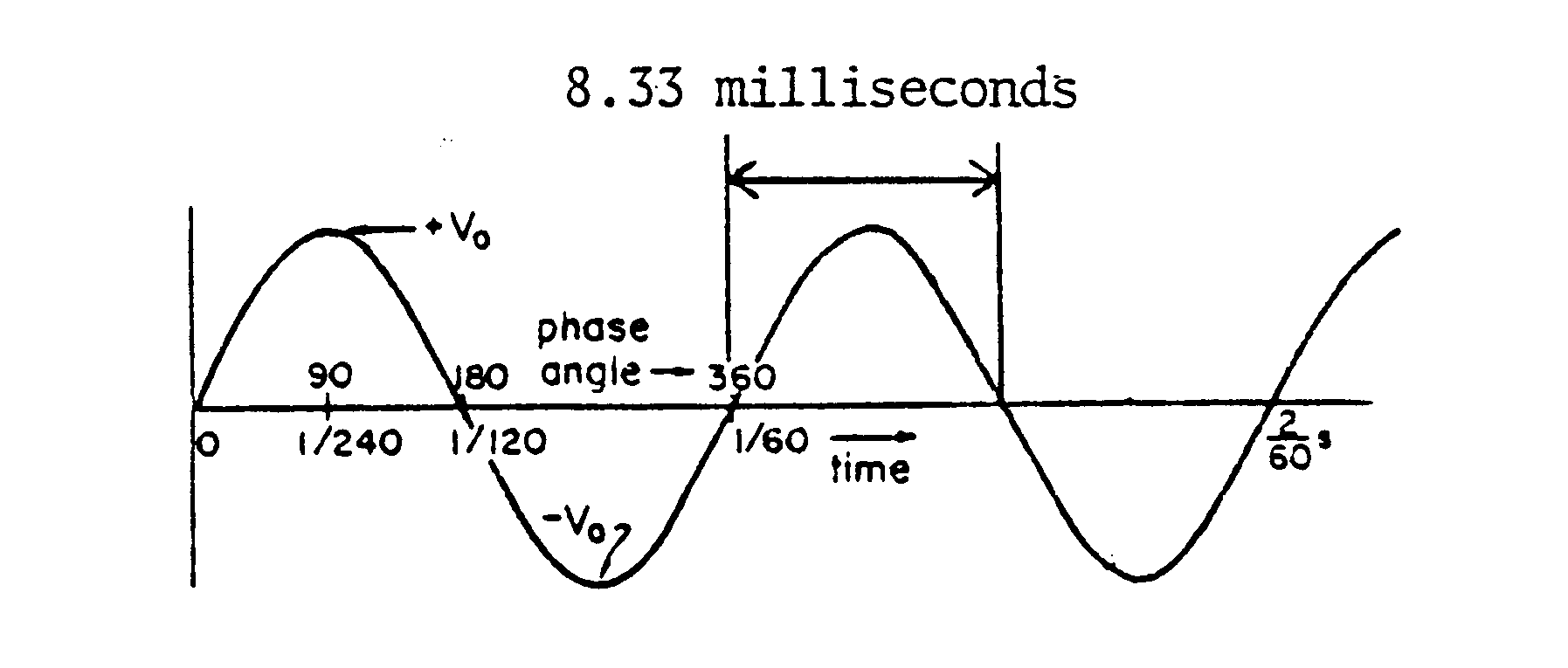
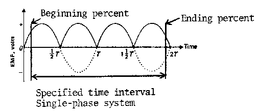
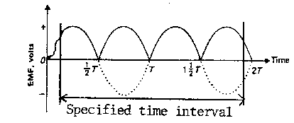
The PULSE EXPOSURE mode (and the PULSE DURATION mode discussed later) are atypical of operational modes usually found on radiation monitors. These modes were specifically designed into the MDH 1015 to evaluate x-ray machine performance in accordance with the Federal standards. In order to understand the operation of the PULSE EXPOSURE mode, consider the x-ray output emerging from a simple single-phase x-ray machine. The voltage waveform supplied to the x-ray system is sinusoidal in nature (Figure 1A), but because only the positive pulses are useful in producing X rays, the circuitry is designed to either clip the negative pulses (half-wave rectified system, Figure IB) or to flip them over to positive pulses (full-wave rectified system, Figure IC).
Figure 1A
Figure 1B
Figure 1C
Thus, the x-ray output is a series of pulses each rising from zero intensity up to a maximum (peak) and falling again to zero.
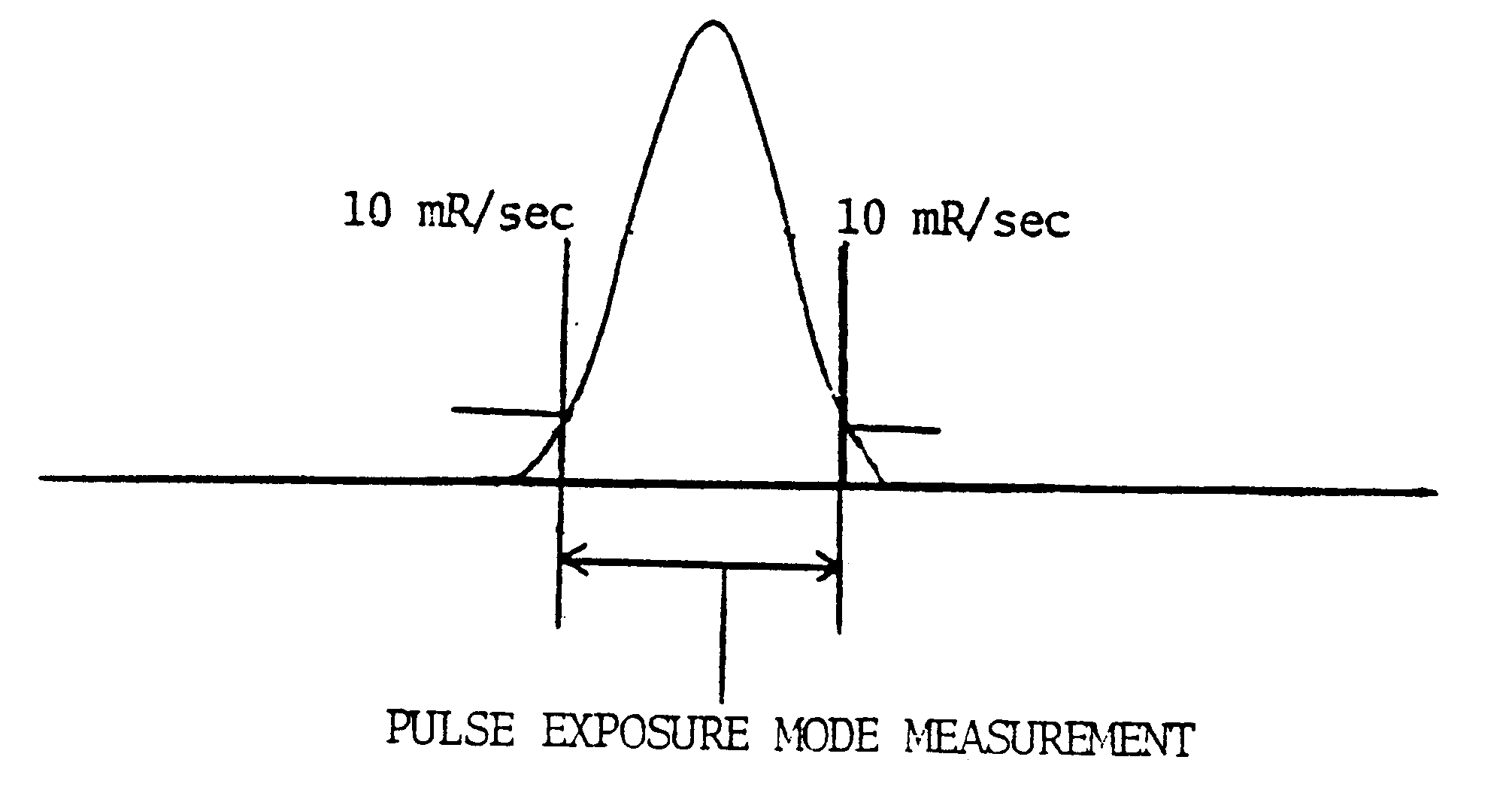
The MDH 1015 is designed to measure the x-ray exposure of such output in the PULSE EXPOSURE mode. When the exposure is initiated and the voltage waveform begins its positive rise, X-rays begin to emerge from the tube. At some point, the MDH 1015 will start to measure the x-ray exposure and will continue measuring until the exposure ends. This beginning measurement point, which was selected and designed into the MDH 1015 by the instrument developers, is where the x-ray intensity reaches 10 mR/sec on the rise, and the ending point is where the intensity drops to 10 mR/sec on the fall (Figure 2).
Figure 2
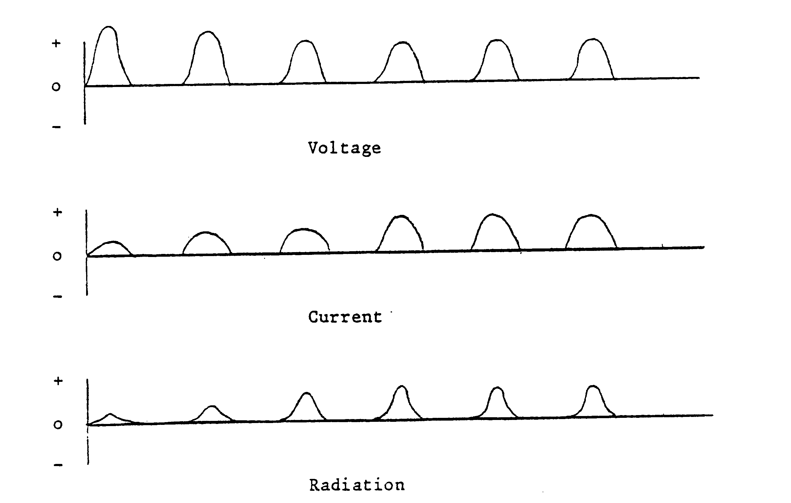
Referring again to Figure 1A, it can be seen that the voltage pulses are only 8.33 milliseconds in duration whereas most routine radiographic x-ray exposure times are in excess of 50 milliseconds, thus a typical x-ray exposure will consist of a number of radiation pulses, each one rising and falling through the 10 mR/sec "trigger" point. How then does the MDH 1015 "know" to count all the pulses in a full x-ray exposure rather than count only the first pulse and then terminate when the intensity drops to 10 mR/sec the first time? This is achieved by a built-in memory buffer and delay circuit. When the MDH 1015 begins measuring (x-ray intensity reaches 10 mR/sec on the rise), it accumulates the exposure until the intensity drops to 10 mR/sec on the fall at which time it stores the accumulated exposure into a memory buffer. The MDH 1015 now waits for 2 seconds to see if any more radiation (second pulse) comes in. If so, it will accumulate the exposure of this pulse and add it to the exposure already in the memory buffer. It will continue this process until no more radiation pulses are detected within 2 seconds of the previous pulse. The MDH 1015 will then display the sum of the accumulated exposures in each of the pulses. The 2 second delay was selected as a reasonable delay time to allow for measuring the exposure of half-wave rectified systems which produce a series of pulses separated by a non-radiation producing gap. The assumption being that any radiation coming into the MDH 1015 within 2 seconds of the previous pulse is considered to still be part of the first exposure, and any radiation detected after 2 seconds is actually a second exposure.
In the PULSE EXPOSURE mode, the MDH 1015 "resets" automatically between exposure measurements. For example, during an exposure, if the exposure rate drops below 10 mR/sec for longer than 2 seconds and then comes back up above 10 mR/sec again, the MDH 1015 interprets this as two separate exposures. It then resets itself after the first exposure and displays the value of the second exposure. This permits the measurement of several, distinct radiation exposures without the total radiation being added together, as it does in the EXPOSURE mode. Since in this mode the instrument does not sum an exposure series, it is possible to take several separate exposures without having to reset the instrument between exposures. This is important, since it is not always convenient to reset the instrument manually.
PULSE DURATION mode
The PULSE DURATION mode provides a means to determine the length of time that the x-ray tube is producing radiation. This mode is a desired feature of the MDH 1015, because before its development, it was necessary to use a separate instrument for measuring exposure time.
The provisions of the Federal performance standards (21 CFR Subchapter J) require manufacturers of x-ray systems to establish and specify the measurement basis for exposure time. This measurement base is generally expressed in terms of percent of the voltage waveform. of the high voltage output through the x-ray tube. Simply stated, the exposure time is the time radiation is produced beginning at a certain percentage of the voltage waveform on the rise until that same percentage is reached on the fall of the last pulse in the exposure interval (Figure 3).
Figure 3
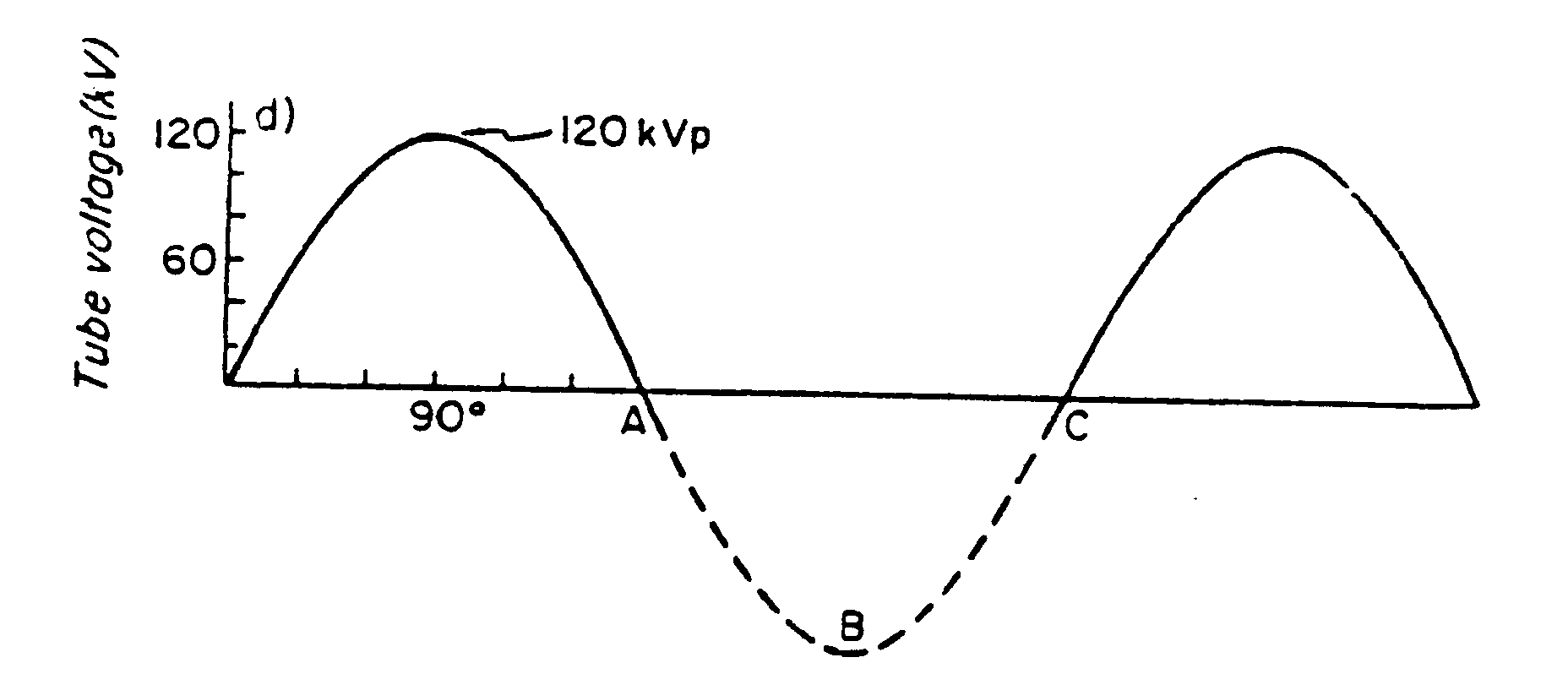
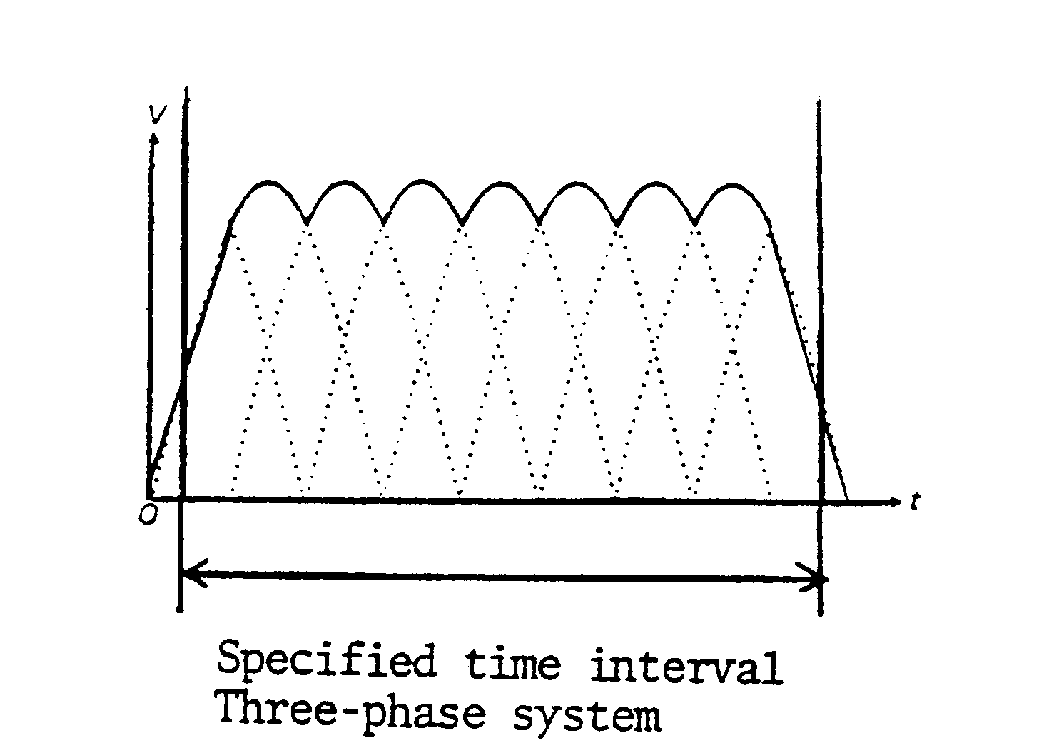
For three-phase systems, there is, in effect, only one long pulse, so the time interval begins and ends at a certain percent of the same pulse (Figure 4).
Figure 4
The Federal standards do not restrict the manufacturer's selection of the measurement base, hence the specified "triggering" percent point may be different for different models of x-ray systems. The selection of the triggering percent point is influenced by several factors such as an asymmetrical first pulse in which the rise of the first pulse is somewhat jagged in shape (Figure 5) and the manufacturer wants to exclude that part of the pulse before starting the timer measurement.
Figure 5
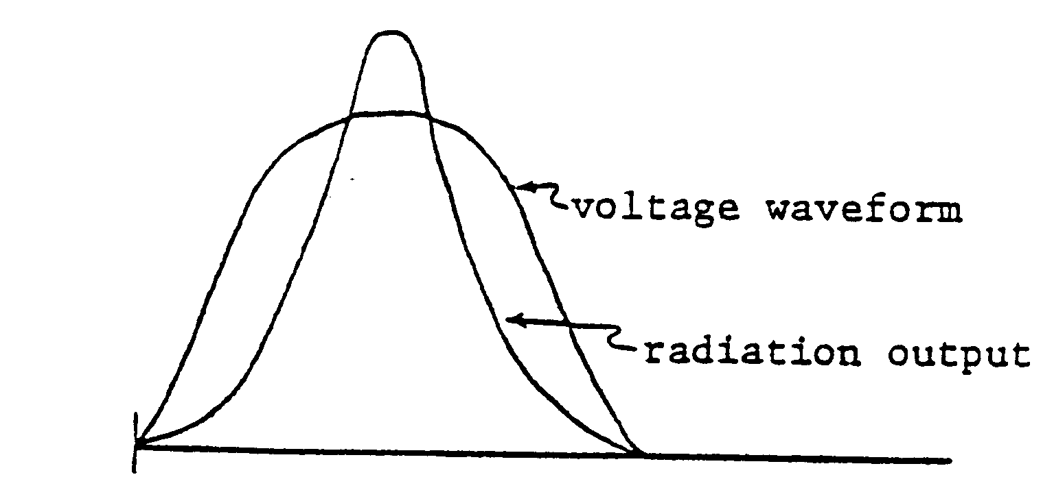
Because the measurement base can vary, it was-necessary to design the MDH 1015 with the capability for measuring the exposure time in accordance with the manufacturer's specifications. This is accomplished by use of the PULSE-FRACTION-THRESHOLD thumbwheel. It is important to note that this thumbwheel works only in conjunction with the PULSE DURATION mode and has no connection to or effect on any of the other three modes. The thumbwheel provides selectable dial settings from 0.1 to 0.9, corresponding to an adjustable range of 10% to 90% of the radiation pulse. Although the manufacturer specifies the time measurement base as it relates to the voltage waveform, the MDH 1015 is only capable of detecting radiation, hence it "triggers" at a certain percent of the radiation pulse (as determined by the thumbwheel setting) rather than at a percentage of the voltage pulse which it is unable to detect. Unfortunately, the shape of the radiation pulse(s) is not the same as the voltage pulse(s). This is illustrated in Figure 6.
Figure 6
From the figure it can be seen that the radiation pulse is not congruent with the voltage pulse but "lags" behind on the rise and drops more rapidly on the fall. This phenomenon occurs because at lower voltages (just as the voltage pulse begins to rise or has reached nearly zero on the fall) less energetic X rays are produced which are readily absorbed in the tube housing glass, beam-limiting device filters, and other components in their path such that the radiation output is low until peak voltages are reached.
Thus, the correspondence between the voltage waveform and the radiation waveform must be known before an accurate measurement of the time interval can be made. This correspondence was experimentally determined and verified in the CDRH laboratories using a single-pulse voltage waveform to correlate the radiation waveform percentages to the voltage waveform percentages. The approximate correspondence between the thumbwheel setting of the MDH 1015 and percent voltage waveform peak height is given in Table 1.
Table I % Voltage Waveform Peak Height Thumbwheel Setting 90 0.7 80 0.6 75 0.5 70 0.4 60 0.2 Knowing this correlation, the MDH 1015 thumbwheel can be set appropriately to measure the time interval as specified by the manufacturer.
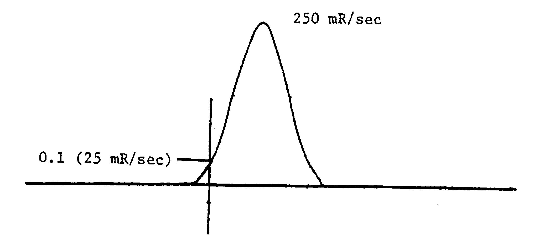
In order to perform a time measurement using the PULSE-FRACTION-THRESHOLD thumbwheel, the MDH 1015 must first "know" what the maximum intensity (peak) is before it can trigger at a preselected percentage of it. This is accomplished in a two step process. In the first step, a test exposure is made in which the MDH 1015 triggers automatically at 10 mR/sec (the same trigger point as in the PULSE EXPOSURE mode), determines the peak intensity of this exposure, and stores the peak value in the PULSE-FRACTION-THRESHOLD circuitry's memory. Now, in the second step, when a subsequent exposure is made, the MDH 1015 will trigger at the preselected percentage of the radiation pulse as established by the thumbwheel setting. For example, consider the radiation pulse illustrated in Figure 7. If the test exposure peak intensity reaches 250 mR/sec, then during the second exposure, if the thumbwheel is set to 0.1, the MDH 1015 will trigger at 10% of the pulse, or 25 mR/sec. The time interval will be measured from this point on the rise of the pulse until the same intensity is reached on the fall of the last pulse in the time interval.
Figure 7
The MDH 1015 provides an indication of this entire process on the digital display. When the mode selector is first put into the PULSE DURATION mode, the display reads - 00.0. The negative sign indicates that the MDH 1015 is ready for the test exposure so it can determine the peak pulse height (intensity). After this initial exposure, the display will show a time reading preceded by a minus sign (for example -438). The negative sign in this case indicates that the MDH 1015 has now determined the peak intensity and stored it in memory. Since a time value is present on the display, the negative sign also acts as a cautionary indicator to inform the operator that the MDH 1015 began its time measurement by triggering at the 10 mR/sec point rather than a preselected percentage via the thumbwheel setting. When a subsequent exposure is made, the display will show a time reading without the negative sign, indicating that the MDH 1015 has now triggered at the preselected percentage determined by the thumbwheel setting. And, as long as the MDH 1015 is not reset, the time interval of any subsequent exposures) will be measured based on the thumbwheel setting. The MDH 1015 is designed so that the mode selector can be switched back and forth between PULSE DURATION and PULSE EXPOSURE without affecting the PULSE-FRACTION-THRESHOLD setting. This is to allow for reading the time measurement and its corresponding exposure without having to start the time measurement process (discussed above) all over again. However, any other switching of the mode selector or function selector will reset the PULSE DURATION mode back to -00.0.
Special Problems with MDH 1015 Measurements
The manufacturer is allowed to specify the measurement basis for timer accuracy. This specification is typically based on the voltage pulse rather than the radiation pulse. Thus, the exposure time is the length of time that power pulses are gated through to the low voltage (primary) side of the high voltage transformer. Since the MDH 1015 measures time based on the radiation pulses generated by the voltage on the high voltage (secondary) side, a discrepancy between the two measurement bases occurs. This discrepancy can arise from three sources as follows:
(1) The "phantom" pulse
(2) Timing threshold
(3) Preheat pulsesThe "phantom" pulse
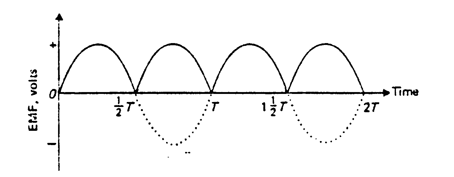
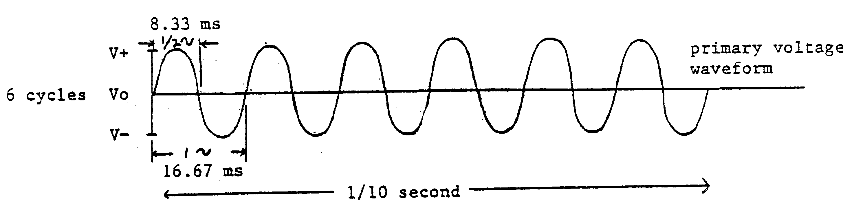
The greatest, but least obvious discrepancy is caused by the "phantom" pulse which results from tests conducted on single-phase half-wave rectified machines, because the negative phase of the wave cycles on the low voltage side produce no radiation pulses on the high voltage side. This affects single-phase half-wave rectified systems only, since both full-wave rectified and three-phase systems electronically convert the negative pulses to positive pulses. To understand how the .. phantom" pulse affects measurement of timer accuracy, consider a 1/10 second (100 ms) portion of voltage waveform from the primary side of a single-phase source.
Figure 8
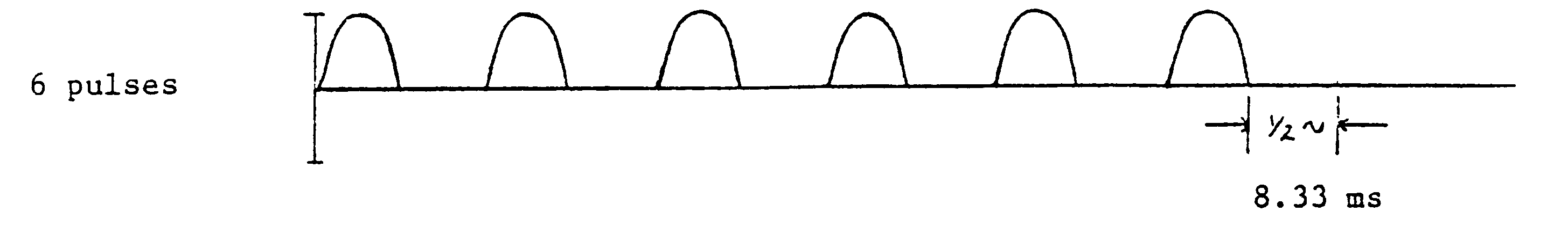
From figure 8, it can be seen that there are six full cycles (at 60 Hz) and each cycle is 16.67 milliseconds long. Since single-phase half-wave rectified x-ray system timers always start counting at a positive going cycle, phase difference at the instant the exposure switch is pressed can be ignored. On the secondary side of the high voltage transformer, the resulting six radiation pulses will be 8.33 ms long each (1/2 cycle) and will be follow by an 8.33 ms "phantom" pulse which has been canceled by the rectification (Figure 9), for a total of 1/10 second (100 ms). However, since the MDH 1015 only sees" radiation pulses, the 8.33 ms negative pulses that do not produce radiation will not be detected. The logic circuit of the MDH 1015 does allow it to count the "negative" pulses that are bracketed by positive pulses (because of the built-in 2 second delay discussed in section II.A.), but not the trailing "negative" pulse. The result is that the time measured will be 91.67 ms. The MDH 1015 will accumulate time only for the period during which positive pulses are present. As a result, the time period during which the last wave cycle is in its negative phase is ignored.
Figure 9
1/10 seconds = 100 ms - 8.33 ms 91.67 ms Timing the radiation pulse and the threshold setting
The second source of disagreement is due to the circuitry within the MDH 1015 that decides when to start and stop timing an exposure, and affects single-phase half-wave and full-wave rectified as well as three-phase x-ray system measurements. This function was designed into the MIDH 1015 to permit accurate measurements in instances where the manufacturer specifies exposure time as that time between certain percentage points of the voltage waveform. (as mentioned earlier in section II.D. PULSE DURATION mode).
Since manufacturers typically specify the exposure time interval based on the voltage waveform whereas the MDH 1015 measures this interval based on the radiation waveform, a discrepancy can exist in the measured exposure time versus the preindicated (or specified) exposure time. This is especially true for single-phase systems where the manufacturer traditionally specifies the exposure time interval as beginning and ending at zero percentage of the voltage waveform (the points where the pulse is just starting or just ending its positive phase) while the MDH 1015 does not start measuring the time interval until a certain percentage of the radiation waveform has been reached as determined by the thumbwheel setting.
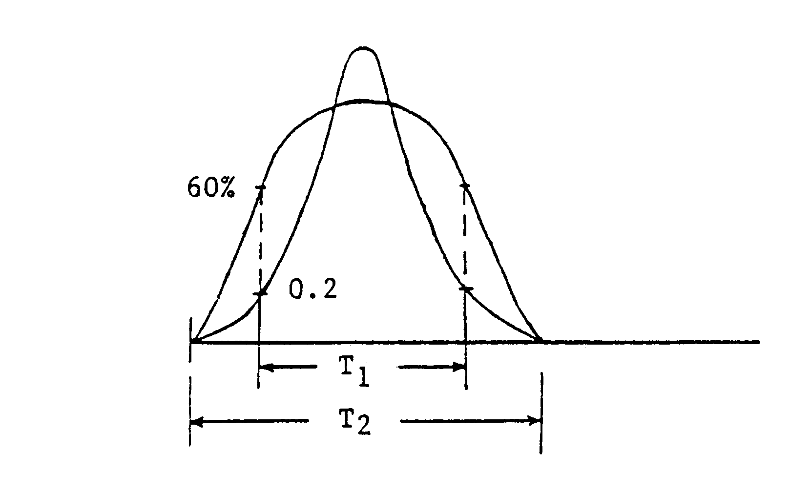
This is illustrated in Figure 10. For example, if the MDH 1015 thumbwheel is set to 0.2 (corresponding to 60% of the voltage waveform) the measured time interval is T1, but the true time is T2. The difference between Tl and T2 can be significant, especially for single-phase systems where the discrepancy can be as much as 4-6 ms. For three-phase systems, the discrepancy is much less and considered negligible. This is due to the fact that three-phase systems produce radiation that resembles a constant source of radiation rather than the pulsed radiation from single-phase systems.
Figure 10
Since the voltage waveform characteristics are quite different from that of single-phase systems, manufacturers of three-phase systems usually specify the exposure time interval as beginning and ending at some percentage, well above zero (typically 75%), of the voltage waveform. In this case, the MDH 1015 thumbwheel can be set to match the corresponding specified percentage of the voltage waveform thus making T1 and T2 the same.
Preheat cycle radiation
Another source of disagreement which can affect the time measurement results from a non-preheated filament. Radiation is produced by the filament, even though it is not hot enough to produce the selected tube current. Although most x-ray systems have a pre-heat cycle, some, such as many dental and small portable systems, do not. For these systems, the first few voltage pulses are high in amplitude due to the low current flow (because the filament is not yet heated enough to "boil" off the maximum number of electrons). This is illustrated in figure 11.
Figure 11
As discussed in section III. B., the manufacturer specifies the time interval based on the voltage pulse whereas the MDH 1015 measures time based on the radiation pulse. From figure 11, it can be seen that while the initial voltage pulses are large in amplitude, the radiation pulses are small. Thus, depending on where the manufacturer specifies the time interval to begin will greatly affect the agreement between the MDH 1015 reading and the indicated time setting. For example, if the manufacturer decides to include the initial pulses in the time interval, the corresponding radiation pulses are so small that the MDH 1015 will not be triggered, and the measured time will be shorter than the indicated time.
On the other hand, if the manufacturer ignores the first five or six pulses before beginning the time interval, the radiation pulses may have already reached sufficient amplitude such that the MDH 1015 is triggered, and now the measured time may be greater than indicated. Because of the wide variation in both the voltage pulse train and the manufacturer's specified timing base for non-preheat filament systems, it is not always easy to establish an absolute value of discrepancy between the indicated time versus the measured time.
- Specific measurements
The timer accuracy test
The timer accuracy test is a simple straightforward test to compare the measured time interval to the indicated time interval of the x-ray system. Any discrepancy is then compared to the accuracy limits specified by the manufacturer since the Standard does not specify timer accuracy limits but requires the manufacturer to state them. The test consists of preselecting a time, taking a series of "exposure duration" measurements with the MDH 1015 and the 6 cc chamber, choosing the one value (of the series) that has the maximum deviation from the preselected time, and computing the percent deviation. This deviation is then compared to the manufacturer's stated accuracy specifications.
Phototimed mode
It is necessary when conducting tests of reproducibility on systems with automatic exposure controls (phototiming) to make sure that the x-ray tube produces radiation for longer than 1/10 second (100 ms). Since 21 CFR 1020.31(b)(2) requires that all reproducibility measurements with phototimed systems be made at exposure times of no less than 1/10 second (100 ms).
If when testing a system for reproducibility in the phototimed mode and the MDH 1015 reads less than 1/10-second, there are certain measures that can taken to make the system produce radiation for a longer period of time. The first thing that should be tried is adjustment of the density control for the phototimer on the main control panel. This density control usually is identified on the unit by the following possible settings: -3 -2 -1 0 +1 +2 +3. The density referred to is the level of film density or darkness. Adjusting this control to a higher value (example: -1 to +2), increases the exposure to the phototimer by increasing the exposure time.
Note that on some systems an increase in the density adjusts some other technique factors such as tube potential or current without increasing the exposure time. If this happens, it might help to reduce the kVp or mA. To get the same radiation to the phototimer, the system may increase the exposure time to compensate.
Another method of increasing the exposure time without adjusting the technique factors is increasing the filtration in the x-ray beam. This will reduce the amount of radiation to the phototimer detector which is similar to having a larger patient on the x-ray table. Many systems will compensate for the reduced radiation by increasing the exposure time.
Fluoroscopic beam quality
It is important when performing the fluoroscopic beam quality test to reset the MDH 1015 between each measurement. As the aluminum sheets are removed from the test stand, the shape of the radiation curve is changed because of the lower energy radiation being included in the measurement. If the MDH 1015 is not reset between exposures, the threshold setting adds an error to the exposure time measurements and will start the exposure reading at different initial exposure rates, depending on each individual radiation curve. By resetting the MDH 1015, the measurement will always start at 10 mR/second and the resulting readings can be normalized using the PULSE DURATION readings for each exposure.
Reproducibility
For beam quality measurements the radiation pulse shape varies depending on the amount of aluminum deliberately placed in the beam, thus it is necessary to reset the MDH 1015 between exposure measurements for the reason discussed in the preceding paragraph. However, during reproducibility testing, no factors affecting the radiation between exposures are changed. Hence, each exposure is affected only by the amount of radiation being produced by the x-ray system for a selected time interval. Therefore, it is important not to reset the MDH 1015 between reproducibility measurements so that accurate measurements of exposure time can be made according to the measurement basis (bases) specified by the manufacturer. For consistency, the MDH 1015 must be allowed to trigger at the threshold setting each time rather than resetting between exposures.
- Physical and mechanical considerations
Barometric adjustment
Some MDH 1015 monitors have a barometric correction knob on the instrument to compensate for barometric pressure at various altitudes. Most of the instruments provided by FDA don't have this control. The reason for not having this compensation on the instrument is that most investigators do not have access to accurate barometric pressure readings. It would add an inconsistent source of error to the radiation measurements if the investigator was unable to determine the barometric pressure for their location and dialed an incorrect setting into the instrument. Another reason is that most of the measurements made with the MDH 1015 on x-ray systems are relative measurements. Exceptions to this are ENTRANCE EXPOSURE RATE on fluoroscopic systems, STANDBY RADIATION on capacitor discharge systems, and TRANSMISSION THROUGH THE IMAGE RECEPTOR SUPPORT DEVICE on mammographic systems. Thus, if one of the measurements in a test is off due to the barometric pressure during relative measurements, all of the other measurements in that test will be off by the same percentage. When a final comparison is made, the results are not affected.
This is not true for ENTRANCE EXPOSURE RATE. Since there are specific values of exposure rate in the Standard, it is important that this measurement be accurate. If there is a drop in barometric pressure from 760 mm Hg to 600 due to altitude, then a radiation exposure rate of 2.00 R/minute will drop to 1.58 R/minute. To get an accurate measurement, it would be necessary to multiply the reading by 760/600 or 1.27.
The result of this problem is that an x-ray system tested at a high altitude may appear compliant with the ENTRANCE EXPOSURE RATE requirement when it's really noncompliant. This has been taken into account in the FDA action levels for entrance exposure rate and the fact that most field tests are conducted at or close to sea level. At higher altitudes, the ENTRANCE EXPOSURE RATE may be slightly underestimated.
When using an MDH 1015 with a barometric pressure correction knob and the pressure in millimeters of mercury (mm Hg) is known, then adjustment of the correction knob to the appropriate setting can be made. However, if the barometric pressure is not known, the unit should be set to atmospheric pressure at sea level (760 mm Hg). Since most MDH 1015 monitors do not have a correction knob, there is no need for adjustment. DO NOT attempt to correct any MDH 1015 measurement values for barometric pressure prior to entering these values on the test record.
- Ion chambers
removing 6 cc chamber from test stand
You will notice on the ion chamber probe assembly that there is a lip at the end of the ion chamber (see figure 12, item B) which can catch the edge of the holes in the test stand when it is being removed from the test stand. Special care must be exercised to keep from pulling the ion chamber off of the probe assembly.
changing ion chambers
It is important when changing ion chambers to observe the design of the MDH ion chamber probe and converter box assembly. As has been indicated in the test procedures manual, the probe should never be twisted or turned, due to the conducting metal pins on the probe connector. Another precaution that should be observed is the fact that the probe connector is spring loaded. Never attempt to pull the ion chamber probe from the converter box assembly without first grasping the probe around the spring-loaded ring opposite the ion chamber end (see figure 12). By sliding your fingers along the beveled portion of the converter box assembly connector (see figure 12, item A) toward the probe, the probe connector ring will compress toward the ion chamber thus disengaging the probe without damaging it. When connecting the probe to the converter box assembly, line up the "black dots on the probe and converter box assembly and push into place until it "clicks".
--] "Figure 12. Image A: Converter Box; Image B: Ion Chamber")
Figure 12
REFERENCES
- Operating and Instruction Manual, 1015F X-Ray Monitor, MDH 1015 Industries, Inc., 426 West Duarte Road, Monrovia, California 91016.
- Memorandum, Measurement of Timer Accuracy for Diagnostic X-Ray Systems, U.S. Army Environmental Hygiene Agency, Aberdeen Proving Ground, Maryland 21010, (1978)
- Error Analysis on Timer Measurements, G.G. Martin, Office of Compliance, Center for Devices and Radiological Health, unpublished.
- Personnel Communication, Michael Divine to Thomas Lee, Office of Science and Technology, Center for Devices and Radiological Health, (1984)