Lumbar Integrated Fixation Devices-Best Practices for Biomechanical Evaluation under Fatigue Loading
Catalog of Regulatory Science Tools to Help Assess New Medical Devices
Technical Description
This tool provides recommended best practices for performing in vitro human cadaver based biomechanical evaluation of lumbar integrated fixation devices (IFDs) under fatigue loading. This tool also describes recommendations for performing multidirectional flexibility assessment of IFD constructs in the intact state, before and after the fatigue loading, to quantify the effect of the IFD on segmental range of motion (ROM). The tool Appendix describes recommendations for:
- Specimen preparation
- Study design
- Biomechanical testing
- Data analysis
Intended Purpose
This tool may be helpful and applicable for medical device manufacturers in evaluating the long-term biomechanical stability of IFDs and evaluating the following post-operative risks:
- Fracture of the IFD or fixation anchors/screws, or both
- Migration of the IFD or fixation anchors/screws, or both
- Damage to the vertebral body
- Insufficient segmental stabilization
Testing
Use of this tool has been demonstrated in the following peer-reviewed publication for comparing long term biomechanical stability of a generic IFD (investigational implant) with a generic anterior plate and cage device (control implant):
- Palepu V, Peck JH, Simon DD, Helgeson MD, Nagaraja S. Biomechanical evaluation of an integrated fixation cage during fatigue loading: a human cadaver study. Journal of Neurosurgery: Spine. 2017 Apr 1;26(4):524-31.
Limitations
This tool provides best practices for the biomechanical evaluation of IFDs under fatigue loading along with multidirectional flexibility assessment of IFD constructs before and after fatigue loading. Extrapolation of this tool to other medical device types may not be appropriate. This tool may not replace the need for clinical data, animal testing, or other methods, as appropriate, and described in documents such as:
- Intervertebral Body Fusion Device - Class II Special Controls Guidance for Industry and FDA Staff
- Standard Test Methods for Intervertebral Body Fusion Devices -ASTM F2077
- Standard Test Method for Measuring Load-Induced Subsidence of Intervertebral Body Fusion Device Under Static Axial Compression - ASTM F2267
Supporting Documentation
This paper describes the recommended loading methods, specimen conditions, and analysis parameters for in vitro human cadaver biomechanical stability testing of spinal implants
- Wilke HJ, Wenger K, Claes L. Testing criteria for spinal implants: recommendations for the standardization of in vitro stability testing of spinal implants. European spine journal. 1998 May;7(2):148-54.
The multidirectional flexbility loading protocol used for our validation study was based on the following papers:
- Cardoso MJ, Dmitriev AE, Helgeson M, Lehman RA, Kuklo TR, Rosner MK. Does superior-segment facet violation or laminectomy destabilize the adjacent level in lumbar transpedicular fixation?: an in vitro human cadaveric assessment. Spine. 2008 Dec 15;33(26):2868-73.
- Agarwal A, Palepu V, Agarwal AK, Goel VK, Yildirim ED. Biomechanical evaluation of an endplate-conformed polycaprolactone-hydroxyapatite intervertebral fusion graft and its comparison with a typical nonconformed cortical graft. Journal of Biomechanical Engineering. 2013 Jun 1;135(6):061005.
- Kornblum MB, Turner AW, Cornwall GB, Zatushevsky MA, Phillips FM. Biomechanical evaluation of stand-alone lumbar polyether-ether-ketone interbody cage with integrated screws. The Spine Journal. 2013 Jan 1;13(1):77-84.
Contact
Tool Reference
In addition to citing relevant publications please reference the use of this tool using DOI: 10.5281/zenodo.7883664
For more information:
Appendix: Step-by-step instructions
1. Specimen Acquisition
- Fresh-frozen human cadaveric spine specimens should be procured from an accredited tissue processing institution.
- Specimen demographics and characteristics (age, extent of degeneration, sex, spinal level, and bone quality) should be reported.
- Strict exclusion criteria:
- Formalin fixation
- Trauma
- Tissue malignancy
- Previous implantations
- Metabolic disease that might affect the spine
- Osteolysis
- Herniated disc
- Bony fractures of the spine
- Bridging bone
- Severe osteophyte growth either at the disc or facets
- Segment immobility resulting from
- Significant disc collapse
- Osteophytes
- Ossified disc or ligaments
- Any other medical history that may adversely affect the mechanical performance of the spine
2. Specimen Preparation
- All specimens should be wrapped in saline-soaked gauze, sealed in double or triple plastic bags, and frozen at −20º C until the time of use.
- Fat and musculature of the specimen should be carefully removed while preserving all ligamentous and bony structures.
- Bone quality assessment, via dual energy X-ray absorptiometry (DEXA) or qCT, should be performed on each specimen to assess the bone mineral density of each vertebral body. It is important to choose specimens with non-osteoporotic (T-score > -2.5) bone quality.
- Two functional spinal units (FSUs) should be isolated from the spinal column. For example, the L2–3 and L4–5 FSUs can be isolated from the spinal column of each cadaveric specimen by dissecting through the L3-L4 disc and carefully separating the L3 posterior elements from the L4. The choice of the FSU levels should be based on the indications for use of the device and worst-case loading scenario.
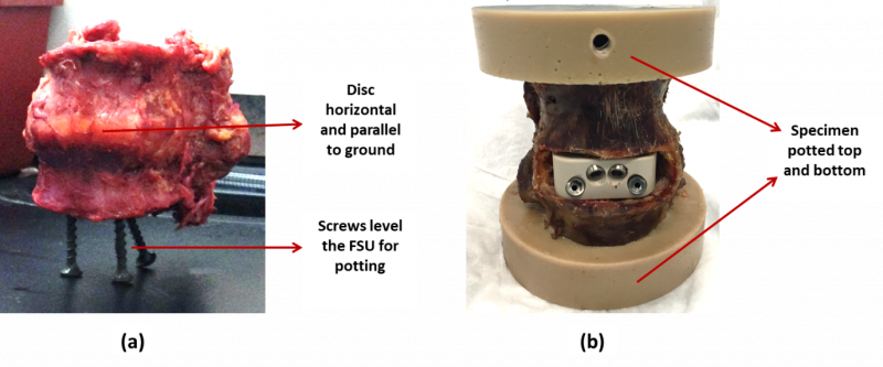
- Segments should be prepared for mechanical testing by potting both cranial and caudal ends in rapidly curing epoxy (or equivalent) per the manufacturer’s instructions. Potting should result in the middle disc being horizontal (Figure 1). Potting and potting fixtures should not impede segment motion in any way (check interference at limits of range of motion). Furthermore, care should be taken to avoid any interference between potting hardware and the IFD fixation screws or anchors.
Figure 1: An example FSU (a) prepared for potting and (b) after potting
3. Implant Preparation
- A control implant should be selected along with the investigational implant to perform side by side testing. The control implant should be FDA cleared for the same indications as proposed for the experimental implant.
- Implant preparation and implantation must be performed with the device-specific instrumentation. Implantation should be performed by board-certified surgeons and should be implanted as per protocol listed in the surgical technique guide for both the control and investigational implant.
- All the investigational implants should be identical to the intended release design with identical geometries and material constituents.
4. Study Design
- Only non-osteoporotic specimens (T-score > -2.5) should be considered for the study.
- The study should have at least n=8 specimens for each implant group. This will allow for a reasonably conclusive statistical analysis. The testing protocol should plan for extra specimens in the event of data loss, specimen failure, or abnormal behavior.
- Intra- and inter-cadaver spine variability (e.g., differences in bone quality and ligament stiffness) can result in substantial variability, which can reduce statistical power necessary to conduct a reliable statistical analysis. This is inherent to cadaver studies and careful selection of cadavers prior to testing is recommended to minimize variability. For example, here are some of the following steps that may help in minimizing such variability:
- L2-3 and L4-5 FSUs from each cadaveric lumbar spine should be distributed to the two implant groups with each group receiving 8 FSU specimens and equal amounts of L2-3/L4-5 FSUs.
- FSU distribution should be performed such that the variations in the specimen related parameters (e.g., age, sex, bone quality, etc.) should be controlled or matched among treatment groups as much as possible to minimize their potential confounding effects (for example, see Tables 1-3 below).
Table 1: Example specimen distribution for the investigational implant group (“S1” means “Specimen 1”)
| Donor ID | Age | Sex | BMI | T-Score | BMD(g/cm2) |
|---|---|---|---|---|---|
| S1-L23 | 69 | M | 31.9 | 1.0 | 1.202 |
| S2-L45 | 72 | M | 14.1 | 1.8 | 1.287 |
| S3-L23 | 61 | F | 24.3 | -0.5 | 1.051 |
| S4-L45 | 71 | M | 26.5 | -1.7 | 0.908 |
| S5-L23 | 85 | F | 27.5 | -1.9 | 0.891 |
| S6-L45 | 81 | M | 20.5 | -2.1 | 0.854 |
| S7-L23 | 70 | F | 28.2 | -2.5 | 0.829 |
| S8-L45 | 70 | F | 15.2 | -0.9 | 0.961 |
| Avg SD |
72 7 |
24 6 |
-0.8 1.5 |
0.998 0.168 |
Table 2: Example specimen distribution for the control implant group
| Donor ID | Age | Sex | BMI | T-Score | BMD(g/cm2) |
|---|---|---|---|---|---|
| S1-L45 | 69 | M | 31.9 | 2.1 | 1.324 |
| S2-L23 | 72 | M | 14.1 | 1.8 | 1.290 |
| S3-L45 | 61 | F | 24.3 | 0.4 | 1.131 |
| S4-L23 | 71 | M | 26.5 | -1.4 | 0.950 |
| S5-L45 | 85 | F | 27.5 | -1.5 | 0.921 |
| S6-L23 | 81 | M | 20.5 | -2.1 | 0.867 |
| S7-L45 | 70 | F | 28.2 | -2.4 | 0.826 |
| S8-L23 | 70 | F | 15.2 | -2.5 | 0.763 |
| Avg SD |
72 7 |
24 6 |
-0.7 1.9 |
1.009 0.213 |
Table 3: Example statistical analysis (Student t-test, p < 0.05) results for specimen age, BMI, and bone quality parameters between investigational and control groups
| Student’s t-test | Age | BMI | T-Score | BMD(g/cm2) |
|---|---|---|---|---|
| P value | 1 | 1 | 0.868 | 0.908 |
- Flexibility testing should be performed on each FSU in the intact, instrumented, and post-fatigue conditions.
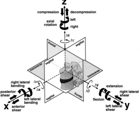
- Cyclic or fatigue testing will be performed on each implanted FSU in flexion-extension (See Figure 2).
Figure 2: Definition of the three-dimensional coordinate system and respective planes of motion (Adapted from Wilke et al., Eur Spine J, 1998)
5. Biomechanical Testing
- Flexibility testing should be performed using a spine simulator or alternative setup (Figure 3) for applying pure and unconstrained moments on FSU specimens in flexion, extension, left lateral bending, right lateral bending, left axial torsion, and right axial torsion loading directions.
- Three loading cycles of ±7.5 Nm should be applied in each loading direction.
- The first 2 cycles should serve as preconditioning cycles to account for viscoelastic effects with data collection on the third cycle.
- An Optotrak Certus motion measurement system (or equivalent) should be used to track relative motion of superior and inferior vertebrae during spinal loading (It is recommended to have the motion be quantified with an accuracy of 0.1 mm and resolution of 0.01 mm).
- Fatigue loading of reconstructed specimens should begin with an initial flexion-extension (FE) loading to ±3 Nm at 1 Hz for the first 5000 cycles and then be increased to ±5 Nm until 20,000 cycles.
- All the specimens should be wrapped in gauze, and phosphate-buffered saline should be sprayed periodically to keep the specimen hydrated during testing.
Figure 3: An example experimental setup. A reconstructed spine specimen is connected to a sliding XY table at the bottom and spine gimbal with 6-axis load cell on top.
6. Data Analysis
A. Flexibility Testing
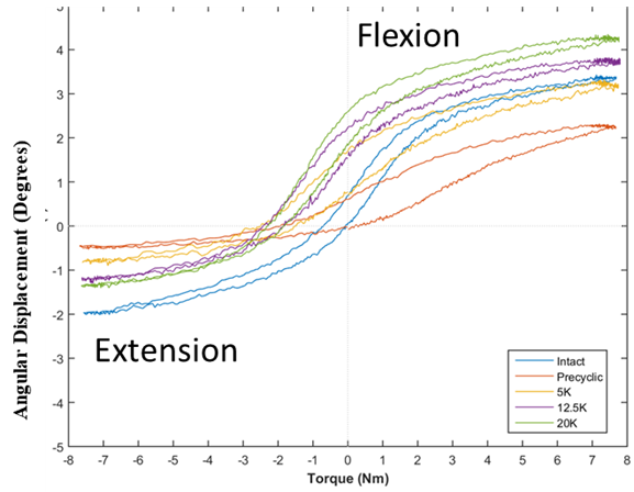
- Range of motion (ROM) should be calculated as the total angular displacement of the final loading cycle for each motion mode (Figure 4).
- Neutral zone (NZ) should be quantified as the difference in angular displacement at zero load between the two phases (flexion and extension) of motion. This parameter is a measurement of the laxity in the spinal specimen without any applied load.
- The lax zone (LZ) should also be quantified by extrapolating a line fit of torque-angle curve (i.e., stiffness) to zero torque. LZ is another stability parameter that describes the region of ligamentous laxity.
- Fluoroscopic images should be taken at all statistically relevant stages of the protocol. For example, before and after intact flexibility testing, before and after instrumented flexibility testing, before and after fatigue testing. Another variation could include flexibility testing at mid-point of fatigue protocol, which would mean fluoroscopic imaging at the mid-fatigue stage.
- Construct loosening should be determined by subtracting the pre-fatigue ROM of the implanted spine for a given specimen from post-fatigue ROM (after 20,000 cycles).
Figure 4: A representative hysteresis loop of a functional spinal unit in flexion–extension in the third cycle of flexibility testing for intact, pre-cyclic, post-5000 cycles, post 12,500 cycles, and post 20,000 cycles.
B. Fatigue Testing
- Peak and valley (minimum and maximum) ROM data should be acquired during cycling, either every cycle, or every n cycles, or logarithmic.
- Video recording of several loading cycles should be performed at all relevant end-points and stages for all groups in the study.
C. Post-Testing
- A gross evaluation of the surgical site and specimen should be performed to determine any unusual tissue or device damage (e.g., subsidence).
- Evidence of any implant damage or loosening should be recorded.
- Micro-computed tomography (micro-CT) imaging of the FSUs shall be performed for quantifying vertebral bone damage caused by the IFD screws/anchors.


