Gravity Flow Rate Testing in Enteral Tubes
Catalog of Regulatory Science Tools to Help Assess New Medical Devices
Technical Description
This in vitro tool describes protocols for enteral tubes gravity flow rate testing and selection criteria for the test fluid.
Note: This tool was previously listed in the Catalog of Regulatory Science Tools to Help Assess New Medical Devices as “Use of Newtonian Analog Fluids and 3D Printing to Evaluate Flow Rates of Diets in G-Tubes.”
Fluid Properties
The tool recommends use of either a glycerin/water mixture with viscosity ≥ 10 centipoise or with non-Newtonian shear thinning clinical diets that exhibit viscosity of > 10 centipoise at clinically relevant rates of 100 s-1 at room temperature. Further details are provided in supporting documentation section.
Flow Rate Testing
For gravity flow rate testing, manufacturers can follow the procedures recommended in FDA-recognized standards ASTM F2528-6 or ISO 20695, or they can refer to the supporting documentation below. The supporting documentation complements the standards and provides additional details on how to perform the testing.
Intended Purpose
The tool provides flow-rate-testing protocols for two scenarios – one in which the manufacturer already has a finished enteral tube, and another in which the manufacturer is currently optimizing their enteral tube design.
The tool can be used to obtain flow rates (in mL/s) for both a predicate device and a subject device. If the flow rate in subject device using the proposed fluids is found to be significantly lower than the predicate device, then it is likely that patients will see a lower delivery rate of nutrition, relative to the predicate device when using the subject device.
Regulatory Evaluation
This tool is intended to compare the gravity-flow-rate performance of the subject device with predicate. It can also be used by device manufacturers currently developing enteral tubes, to optimize the connector section of the enteral tube design. This tool does not replace other special controls or other design requirements discussed in FDA-recognized standards ASTM F2528-6, ISO 80369-3 and ISO 20695.
Regulatory Background and Intended Population
The test protocol applies to enteral tubes with product codes PIF and KNT. Such devices are typically placed percutaneously and connected to the stomach through an established gastrointestinal stoma tract. These devices are used for enteral feeding, medication administration, or decompression for both adult and pediatric patients.
Testing
This tool offers three different test protocols for device manufacturers and developers who:
- want to choose a fluid for gravity flow testing for their predicate and subject G-tubes should refer to protocol P1 listed in the attachment.
- are planning to use their finished G-tubes for flow-rate testing can either refer to FDA-recognized standards ASTM F2528-6, or ISO 20695, or can alternatively refer to protocol P2 listed in the attachment.
- do not have a finished G-tube, who are developing new G-tubes using the FDA-recognized ISO 80369-3:2016 standard and would like to perform testing to optimize their G-tube design should refer to protocol P3 listed in the attachment.
Given the simple nature of the tests and sample preparation, proficiency in wet lab is not required.
Limitations
This tool is based upon research conducted by the FDA in response to observations that tests involving gravity-driven flows of water in enteral tubes do not accurately simulate real-world conditions.
This tool should not be used with enteral fluids that are not well blended, as the particulates may clog the enteral tubes and influence flow rate testing results.
Supporting Documentation
Detailed Methodology
See instructions in Appendix below.
References used for this tool
- The following publication demonstrated that gravity-flow-rate testing with water is not worst case and that testing should be performed with nutritional diets:
Guha S., Ravi N., Silverstein J.S., Cooper J.C., Myers M.R., In vitro Performance Testing of Legacy and ENFit Gastrostomy Tube Devices Under Gravity Flow Conditions. Journal of Parenteral and Enteral Nutrition. 2018, 42(8): 1334-1341. - The following publication demonstrated that glycerin-water mixtures can act as useful surrogates for nutritional diets in gravity-flow-rate testing. It also provides methodology for flowrate testing during the development phase of an Enteral tube, performed to optimize the connector section and minimize reduction in flow rates through devices:
Guha S., Herman A., Herbertson L., Antonino M.J., Silverstein J.S, Cooper J., Myers M.R., Technical Considerations for medical device manufacturers when designing gastrostomy tubes (G-tubes) using the new ISO 80369-3 connector. Plos One. 2020, 15(7), e0236644.
Additional resources for informational use only
Gravity flow testing with blenderized diets
Guha, S., Bouhrira, N., Antonino, M.J., Silverstein, J.S., Cooper, J., Myers, M.R., Impact of Design Changes in Gastrostomy tube (G-tube) devices for patients who rely on home-based blenderized diets for enteral nutrition. Journal of American College of Nutrition. 2019, 38(4): 311-317. Link:
Invited review of current literature on ISO 80369-3 based Gastrostomy tubes and their performance
Guha, S., Herman, A., Antonino, M.J., Silverstein, J.S., Venkataraman-Rao, P., Myers, M.R., Synthesis of research on ENFit gastrostomy tubes with potential implications for US patients using these devices. Nutrition in Clinical Practice. 2022.
Contact
Tool Reference
In addition to citing relevant publications please reference the use of this tool using DOI: 10.5281/zenodo.7558776
For more information:
Appendix: Step-by-step instructions
Protocols for Preparing Fluids and for Determining Flow rates in Enteral Tubes by Device Manufacturers
SUMMARY
Device manufacturers who want to choose a fluid for gravity flow testing for their predicate and subject G-tubes should refer to protocol P1 below.
Device manufacturers who are planning to use their finished G-tubes for flow-rate testing can either refer to FDA recognized ASTM standards F2528-6, or ISO 20695, or can alternatively refer to protocol P2 below.
Device developers and manufacturers who do not have a finished G-tube, who are developing new G-tubes using the FDA recognized ISO 80369-3:2016 standard and would like to perform testing to optimize their G-tube design should refer to protocol P3 below.
PROTOCOLS
P1. Fluids for Testing
Manufacturers can use any one of the following fluids for gravity flow rate testing1,2 -
- OsmoliteTM 1.0 (Abbott Nutrition, Columbus, OH)
- Boost TM (Very High Calorie) (Nestle Healthcare Nutrition Inc. Florham Park, NJ)
- Glycerin-water mixtures with viscosity in the range of 10 – 100 centipoise prepared following instructions provided elsewhere3. An excerpt from that reference is provided below at room temperatures of 20 and 30 oC in Table 1. As an example, if testing is performed at 20 oC then adding 60% by weight glycerol to 40% water would yield 10.8 centipoise.
Table 1. Glycerol % weight to use for achieving 10 – 100 centipoise in the 20 – 30 oC temperature range3
| Glycerol % weight | Viscosity of Aqueous Glycerol Solutions (centipoise) Temperature (20 oC) |
Viscosity of Aqueous Glycerol Solutions (centipoise) Temperature (30 oC) |
|---|---|---|
| 60 | 10.8 | 7.19 |
| 65 | 15.2 | 9.85 |
| 85 | 109.0 | 58.0 |
| 90 | 219 | 109 |
As seen from Table 1 fluid viscosities typically demonstrate strong dependence to temperature. Therefore, we recommend that the viscosity of the chosen fluid be measured in a controlled room temperature environment. If the laboratory temperature lies in between 20 – 30 oC, the table above can be used for interpolating the desirable viscosity. Alternatively, a calibrated viscometer should be used for measuring the viscosity of the glycerin water mixture. Before measuring the viscosity of the fluid, it may be desirable to first run a control sample in the viscometer to verify that its functionally operating correctly.
If device manufacturer plans on using a fluid that is not listed above then they should consider the following: for some fluids also referred to as non-Newtonian fluids, viscosities change with shear rate. If the viscosity reduces with increasing shear, they are referred to as non-Newtonian shear thinning fluids. Prior studies determined that nutritional diets used clinically for delivering nutrition through G-tubes are non-Newtonian shear thinning liquids1,2. Based on prior studies1 we recommend that testing be performed with fluids listed above, or with non-Newtonian shear thinning clinical diets that exhibit viscosity of > 10 centipoise or higher at clinically relevant rates4 of 100 seconds-1 at room temperature.
P2. Measuring Flow rate in Gastrostomy tubes
As part of research collaborative agreement with Global Enteral Device Supplier Association (GEDSA), FDA and Mayo Clinic received the protocol from one the device manufacturers. FDA made some modifications to this protocol and used it for obtaining the experimental results published elsewhere4. This section outlines the protocol in detail.
- An empty bolus syringe is mounted in a test clamp at typically at 18” from the top of the syringe to the tabletop an empty beaker is placed below the device.
- A beaker is then placed to receive the fluid that would flow out of the device.
- The G-Tube device is then attached to the syringe. The G-Tube needs to be clamped either with a hemostat (for standard type G-Tube devices) or with its own clamping system (for low profile G-Tube devices).
- 60 mL of the fluid is then poured into the syringe at room temperature.
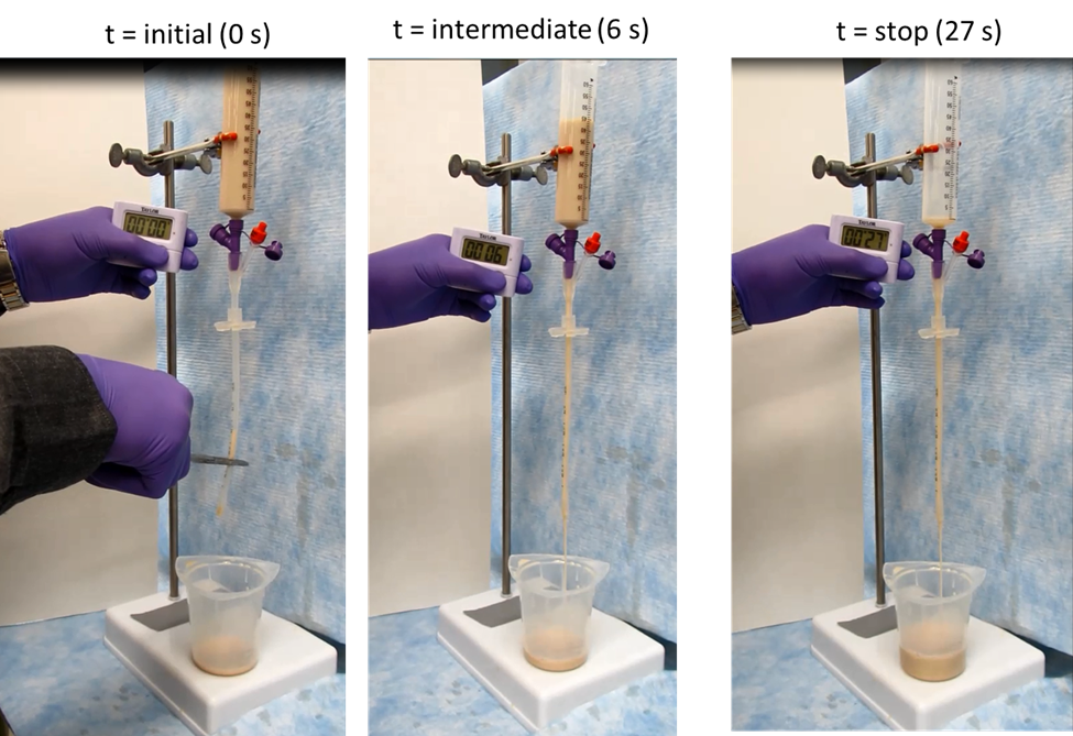
- The clamp or the hemostat on the G-Tube device is released and a timer started simultaneously (Figure 1A).
- The timer stays on for few seconds (Figure 1B) and once the fluid flow runs out of the device the timer is stopped and the time recorded (Figure 1C).
- The flow rate is then calculated in mL/s by dividing 60 mL with the time recorded for dispensing the entire fluid.
- The G-Tube devices, the beaker and the syringe can be cleaned by passing water repeatedly. This is not a necessary step if the user prefers to dispose their device after each experiment.
- Steps 1 to 8 can then be repeated for a new set of G-Tubes with syringes. This testing should be performed with a statistically significant sample size.
- Same steps would need to be repeated with predicate devices.
P3. Designing G-tubes using the ISO 80369-3 connector
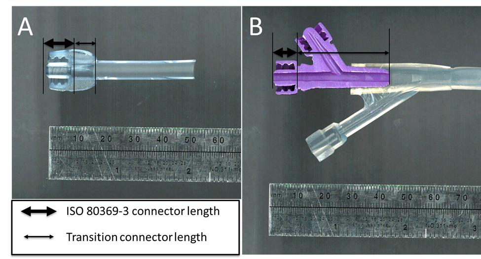
This protocol is for those medical device manufacturers who have not finalized their G-tube design. As demonstrated in prior publications1,2, using the ISO 80369-3 can result in slowing of gravity flow rate compared to some predicate designs. A study was subsequently conducted1 to show that keeping the transition connector section post ISO 80369-3 connector short (≤ 10 mm) helps reduce the slowing of flow rate. In this regard, Figure 2 below shows two examples with actual devices. One has a short transition section (A) while another has a longer transition section (B). The study also showed that any slowing in gravity flow rate can be compensated with some increase of the internal diameter of the distal section that comes after the transition connector as well.
Figure 2(A) Cross-section of a G-tube with an ISO 80369-3 connector followed by a short transition connector length (B) Cross-section of a G-tube with an ISO 80369-3 connector followed with a long transition connector length
The step-by-step protocol for designing a G-tube and to assess the impact of its connector on the flow rate is provided below:
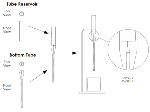
- Prepare CAD designs of a surrogate tube and a reservoir with FDA recognized connector such as ISO 80369-3, and a specific passageway downstream of the connector (Figure 3). Some such examples are provided elsewhere4
- Print/manufacture physical versions of those designs. The physical parts should have surface properties (e.g., surface roughness, hydrophilicity etc.) that are like that of the properties expected in the finalized design.
- Attach the reservoir that can hold at least 60 mL of fluid on top of the surrogate tube (Figure 3). Note that the internal passageway of the reservoir should be the same across all surrogate tube designs tested to minimize its influence on the testing.
- Then place beaker to receive the fluid that would flow out of the surrogate tube-reservoir assembly.
- Fill tube-reservoir assembly with test fluid to remove air from the tube, once air is purged from the tube with the test fluid, plug the bottom of the tube assembly. Note that the presence of air, or separation of the fluid while flowing through internal passageways of the device can significantly impact the repeatability of test results.
- Fill the reservoir with 60 mL of the test fluid at room temperature.
- Remove the plug from the bottom of the tube and start the timer simultaneously.
- Once the fluid has drained from the tube, stop the timer, and record the time elapsed. The flow rate can then be calculated in mL/s by dividing 60 mL with the time recorded for dispensing the entire fluid.
- Dispose of the test fluid in the beaker, clean the test assembly and the beaker.
- Repeat steps 1 to 8 for all tube-reservoir assemblies in triplicates to determine internal passageway of the tube that yields the maximum flow rate (if desirable) and choose surrogate tube that is equivalent to the flow rate in the predicate.
- Finalize G-tube design based on the chosen surrogate tube, or redesign G-tube if flow rate is not equivalent to predicate.
In this regard, choosing predicates that have no, or small transition connector length or ISO 80369-3 connector length (≤ 10 mm) may be most appropriate. More details about ideal predicates that have the highest flow rates is provided in prior publications.1,4
Figure 3. CAD drawings of reservoir and tube with the later designed with ISO 80369-3. These components are meant for mimicking the syringe, and the standard G-tube, respectively. These designs can be printed to create physical parts and then put together for gravity flow testing as shown on the right. The blow-up on the right shows the ISO 80369-3 section of the bottom tube. Using such feasibility studies can help optimize the connector and the downstream section of the G-tube so any loss from the ISO 80369-3 connector can be compensated.
References for the Protocol
1. ISO 80369-3:2016 Small-bore connectors for liquids and gases in healthcare applications – Part 3: Connectors for enteral applications
2. Segur et al., Industrial and Engineering Chemistry, 43(9), 1951, pp 2117-2120
3. Guha et al., Plos One, 15(7), 2020, e0236644
4. Guha et al., Journal of Parenteral and Enteral Nutrition, 42(8), 2018, pp 1334-1341


